 |
|||||||||||||||||||||||||||||||
Concrete Formwork for Suspended Slabs and Beams
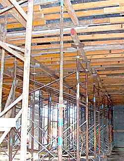
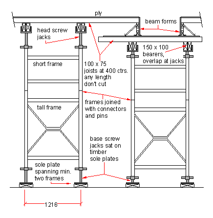
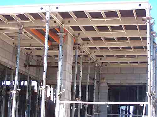
Concrete formwork using Acrow "V-shore" or similar.
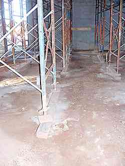
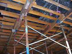
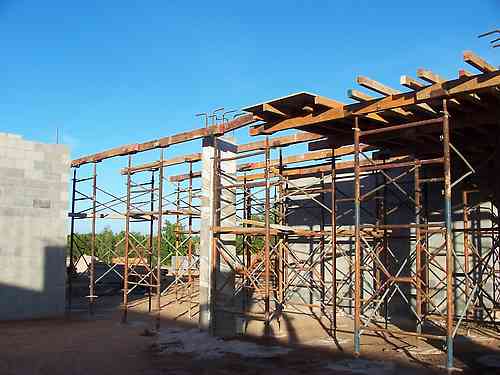
What you see is a series of steel frames with cross braces holding them together. They have adjustable screw jacks at the bottom and top. The top jacks carry heavy timber bearers, (150 x 100) at say 1200 centres which in turn carry joists (100 x 75) at 400 centres. At the base of the frames there are heavy timber pieces called sole plates. The main purpose of the sole plates is to spread the load of the frame to the ground. In this instance they are sat on the building pad, which is a stable pad of compacted earth and then road gravel that forms a base for the building work. On the next floor up, the frames will be sat on the concrete floor, but the sole plates will still be used. Apart from spreading the load on the frame legs, the plates also have a function of stopping the frames moving around under vibration. This is particularly important with say a row of single steel props. The sole plate not only spreads the load and provides a firm base for the prop, but a couple of nails through the prop into the timber sole plate keeps the prop steady under vibration.
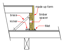
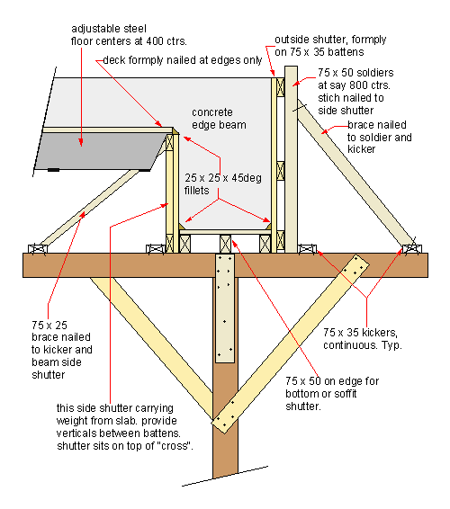
I have put a larger detail of the side form for a beam here. Some times they can be quite deep, so there may be a need for braces. An important detail, are the provision of vertical spacers between the timbers making up the side form. Say at 600 centres these transfer the load from the top ply down to to next layer. Without them the weight on the upper joists could push the top timber off the ply. Here's a few points that come to mind when using this sort of system.
Here's a section of the job in the early stages. You can see temporary planks here and there for the guys to stand on while they are fixing the joists. There will be a laser level set up at the side somewhere and as the frames are fixed the screw jacks will be brought up to level.
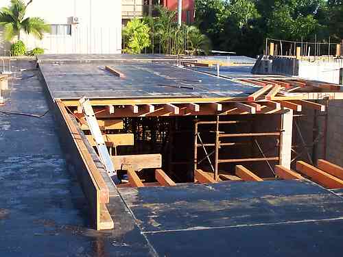
Here's a shot of the job from the top. back to top A Low Tech Way To Do Concrete Formwork for Slabs and Beams
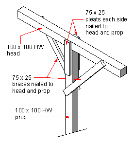
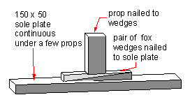
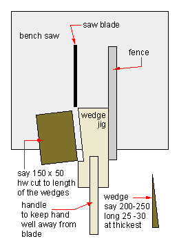
We also could use the timber cross and beam shutters on their own, just to form up beams. We never left the floor centres supported at the ends only. There was always a least one timber bearer with props supporting the centres also, to take a lot of the weight off the cross props shown above. The main support for the beam and edge of slab was what we called a "cross" which is sketched out to the right. These were made up out of sawn hardwood timber, usually, but I have worked on jobs where we used "bush props" with the main prop consisting of 100 to 150m dia sapling trees. Typically they were set up at 1200 centres. (Depending on loads they could be closer of course.) At the bottom, we used "fox wedges" to adjust for height. These along with timber packers as needed were quite adequate. The beam soffits were set up on the cross props between columns. The cross props were nailed at the top to the shutters, they were nailed at the bottom to the sole plates, and unless they were fairly short, we used to nail 75 x 25 braces on them in the middle also. I once did a job that some comedian nailed a ply sign on the outside, "Bill's Jungle". It didn't bother me at all, I'd sooner be seen as the guy who put too many props and braces in. than remembered as someone who didn't do enough.
Easily made up out of a bit of scrap timber.
back to top A Modular Panel system
Here is another system for forming slabs. This type of modular system works well for simple plans, as here where the slab is spanning between concrete blockwork walls, and there is no requirements for forming up beams within the slab. back to top Ring Beams on Brickwork.
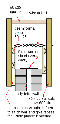
Here is what we used to do at the top of a cavity brickwork wall. For a small one off job I would use the wire tie as detailed, but if I was doing a couple of repetitions, I would buy some 12mm threaded rod and nuts and washers. The reason I have shown the wire above the forms is that the concrete is usually not very deep and this way is sufficient, and there is no need to chip the wire back, like it would e if it was embedded in the concrete. If you decide to put the ties lower, be very careful not to put too much pressure on the top course of bricks. It is very easy to dislodge them, as usually the brickwork has only been laid a few days before. Not found it yet? Try this FAST SITE SEARCH or the whole web |
Hire Equipment  Furniture Fittings - Architectural Hardware - Electronic Locking Systems - Technical Hardware BuilderBill sponsorship Other Formwork Pages.
|
||||||||||||||||||||||||||||||
|
|
|||||||||||||||||||||||||||||||
|
Please Note! The information on this site is offered as a guide only! When we are talking about areas where building regulations or safety regulations could exist,the information here could be wrong for your area. It could be out of date! Regulations breed faster than rabbits! You must check your own local conditions. Copyright © Bill Bradley 2007-2012. All rights reserved. |
|||||||||||||||||||||||||||||||
